Description
ETAP 21 Series offers an impressive new set of integrated power analysis modules, electrical dimensioning capabilities, automation, and operations solutions.
From advanced renewable energy modeling, safety compliance, simulation tools, leading-edge model-driven real-time network management solutions, ETAP 21 addresses your requirements and industry needs.
ETAP 21 Series includes new solutions & features plus 1,000’s of enhancements and time-saving improvements supporting our customers with technology and best practices to become more:
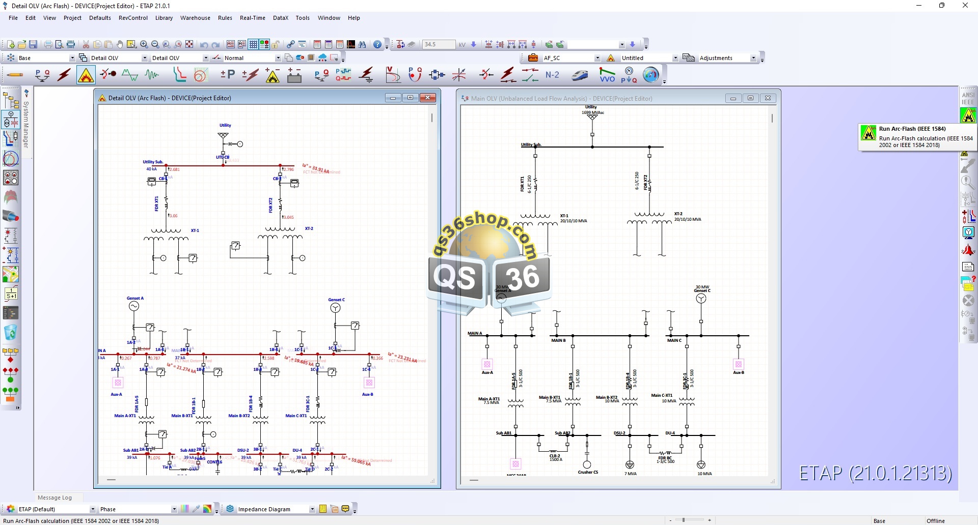
AC Arc Flash
Reduce Risk, Improve Safety & Enforce Compliance based on Australian Std.
Compliance with guidelines for the selection, use and maintenance of PPE for electrical arc hazards
- Calculation based on Australian Std. Energy Networks Association’s ENA NENS 09-2014 (Sweeting Method)
- Maximum and Minimum Arc Current Incident Energy Results
- User-Definable Arc Current Determination Factors
- 3-Phase/1-Phase, Electrode material, and Distance Exponent Factors
- PPE Breakthrough ATPV Multiplier factor
- Batch calculation for 1000’s of locations
- Edit, customize, and Print Labels from the Calculator
- Arc-Flash Boundary and Shock Risk Assessment Plots
- IE vs. Arc Duration and Working Distance Plots
- Enclosed and Open-Air Typical Input Data (per IEEE 1584)
- Arc-Flash Label Templates per ENA NENS 09
Arc-Flash Plot View
Transient Arc-Flash Result Graphical Comparison
- New plots with a quick overview of multiple scenario results
- Incident Energy vs. Working Distance and Arc Duration Lookup Chart
- Worst-Case Arc-Flash Boundary vs. Electrode Configuration Plot
- Transient Arc Current and Incident Energy Plots
- Generic Transient Short-Circuit Bolted Fault Current Input Parameters (Generated)
- Import Transient Short Circuit results to Integrate final Incident Energy Exposure
- Ability to include asymmetrical current in Energy Integration
- PlotView feature includes fully customizable plots including 3D Views
- Unlimited Plot Customization ETAP Plot SnapShots™ to record and save unlimited plot views
- Result Tooltips to aid in Result Visualization
DC Arc Flash
Reduce Risk, Improve Safety & Enforce compliance based on German Std.
Identify and analyze high-risk arc flash areas with greater flexibility by simulating and evaluating various mitigation methods.
- DC Arc Flash Calculator with Two Methods:
- DGUV-I 203-077 – Worst Case (Max Power)
- General (Iterative) – Based on Stokes
- Shunt and Series DC Arc Fault Types
- Batch Import and Export for 1000’s of Locations
- DC Arc Flash Custom Label Generation
- PPE Evaluation based on VDE 0682-306-1-2 or User-Defined Energy Levels
- Typical Input Data for Diff. Equipment Types
- Electrode Material Correction Factors
- Boundary Plots & Intuitive Easy-to-Use Interface
- Export Results to CSV and MS Excel
Reliability Assessment
Assess the availability and quality of power supply at each customer service entrance
- Analyze complete system or targeted feeders only
- Display assessment results directly on GIS Diagram
- Enhanced plot selection
Switching Optimization
Automatically determine the optimal system configuration to achieve user-specified objectives
- Alert & Visual Display on ETAP One-line & GIS Diagram
- Enhanced modeling for switched capacitor banks
Switching Sequence Management
Ensure safety by graphically building, simulating & testing switching sequence plans
- Validation of switch plans using Unbalanced Power Flow
- Simulate switch plans on One-line or GIS Diagram
- Export sequence plans to MS Excel
- Export plans to online Sequence Management Viewer
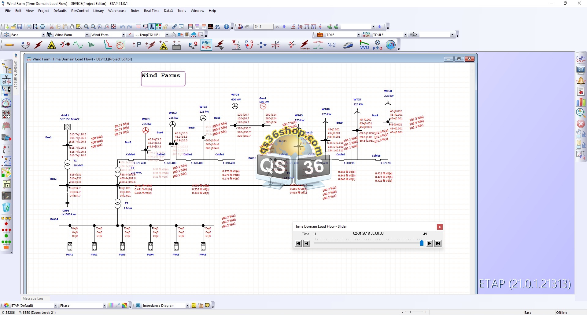
Time Domain Load Flow
Automatically & sequentially vary load and generation and solve steady-state power flows over time
- Quasi-Static Load Flow (QSLF) with Controller dynamics simulation
- Smart Inverter simulation and analysis
- Time-domain profiles for VFD, induction, and synchronous machines
- Plot response from Controllers and SVC/STATCOM
- Total Active & Reactive Power Plots
- Time Slider & Alerts for GIS Diagram
- Interpolation between time steps smaller than profile resolution
- Higher resolution time step external data support and simulation
Signal Scope Analyzer
Signal analyzer allows plotting and analysis of signals from various ETAP modules in multi-module studies
- Analysis and filtering capability for undamped, overdamped, and underdamped signals
- Study Plot Lists capability which allows the user to conveniently select specific plots to be generated and analyzed for their project
- Comparison Signal Instruction files in XML format to support ETAP users with any regional settings
- Unlimited plot customization with ETAP Plot SnapShots™ for single and comparison charts to record and save unlimited plot views
Volt/Var Optimization
Minimize VAR Losses and Improve Distribution Grid Efficiency
- Alert visualization on GIS Diagram
- Enhanced modeling for switched capacitor banks & distribution transformers
StarZ™ Distance Protection
Gain insight into line protection, relay performance & evaluate system-wide protective device operation
- Simulate protection impact based on Unbalanced Faults -AG, BG, CG, AB, BC, CA, ABG, BCG, and CAG
- StarZ™ integration with eTraX™ for railway system protection simulation
- Create and Manage StarView TCCs in StarZ mode
- Normalized TCC based on StarZ Single-fault report
Transient Stability
Accurately simulate power system dynamics and transients
- Frequency calculation for grid-forming inverter
- Improved frequency estimation algorithm for dynamic simulation
Cable Systems
Calculate optimal and alternative cable sizes
- Selection of cables based on Australian Standard AS/NZS 3008.1.1 up to and including 0.6/1 kV
- Selection of cables based on New Zealand Standard AS/NZS 3008.1.2 up to and including 0.6/1 kV
- Built-in ampacity/capacity & derating factor tables based on methods of installation
- Sizing of phase conductor based on loading, voltage drop, short-circuit, and harmonics
- Batch cable management & dimensioning from Cable Manager
- Updating Equipment Cable SC kA from Load Terminal Fault
- Cable pulling upgraded to a 64-bit application
Line Ampacity Calculation
Calculate the current-temperature characteristics for overhead lines
- Comply with IEEE 738-2012 standard
- Study conductor ampacity vs. temperature characteristics
- Determine maximum transmission & distribution line operating temperature under various loading conditions
- Calculate transmission and distribution line derated ampacity based on temperature limit
- Consider effects and adjustments due to weather, solar heat, & geographical location effects
DataX™
Accelerate digitization and data exchange through built-in conversions
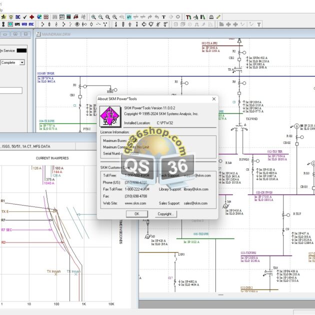
SKM Import
- Enhanced built-in conversion from SKM PowerTools® to ETAP, including conversion of DC system
- Improved automatic single-line diagram generation
Power Analytics / EDSA Import
- Built-in conversion from Power Analytics® / EDSA®
- Automatic single-line diagram generation
Common Information Model Import
- Import & automatic GIS diagram generation from CIM XML
- Incremental data exchange with intelligent component property comparison
- Automatic file ingestion using file watcher and scheduler with job logging
- Automatic device warehouse creation
- Automatic single-line diagram updates for the modified area without impact to non-changed areas
- Automatic synchronization from GIS to single-line
NTF Format
- Built-in conversion using NTF file format for transfer of geospatial information (BS 7567)
- Import data from Distribution Network Information System (DINIS) using NTF format
Release Highlights
Design, Analysis & Simulation
- iSLD Intelligent Single-Line Diagram
- Geospatial Intelligent System (GIS)
- Switching Optimization
- Quasi-Dynamic Load Flow
- T&D Overhead Line Ampacity based on IEEE Std. 738-2012
- Smart Inverters with autonomous functions for DER simulation
- DataX™ Power Analytics / EDSA Import
- ArcSafety™
- AC Arc Flash Calculator based on ENA NENS 09-2014
- Arc Flash Calculator enhancements based on DGUV Std. 203-077
- Cable Sizing
- Australia & New Zealand Std. – AS/NZS 3008
- French Std – NF C15-100

