Description
We are excited to introduce the latest version of our software platform – Planmeca Romexis® 6.2. The 6.2 release includes all-new features, such as the Romexis® 3D Cephalometry module for performing cephalometric tracing and analysis in 3D, as well as improvements to existing functionalities. For example, the Romexis® CMF Surgery module for orthognathic surgery planning has been updated to make it even more intuitive and easy to use.
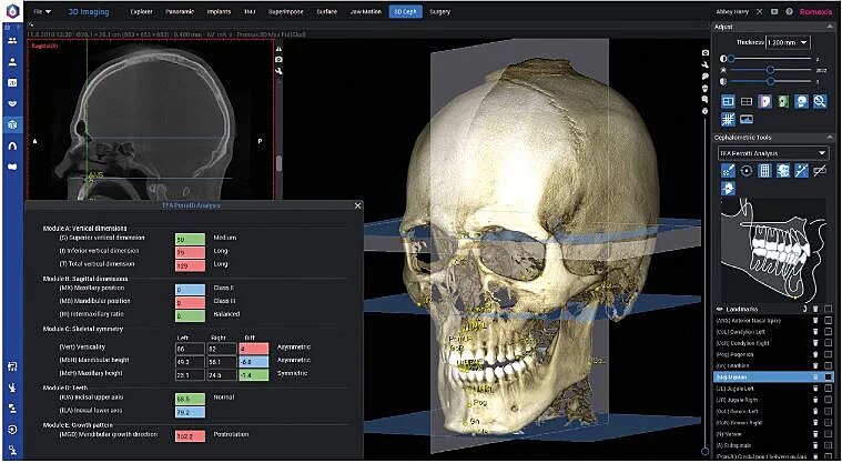
3D Cephalometry module
Romexis® 3D Cephalometry is a completely new Romexis® module for performing cephalometric analysis in 3D. The purpose of Romexis 3D Cephalometry is to maintain all the positive aspects of conventional 2D analysis, such as the landmarks, measurements and their comparison against the norms, and in addition to that, to provide reliable information regarding the morphology, position, and orientation of anatomical structures via specific reference planes and points in 3D. It is a tool that enhances orthodontic CBCT diagnosis by establishing a clear and intuitive graphical representation of the case.The new module works seamlessly with the Romexis® CMF Surgery module allowing the user to continue to surgical planning directly after the 3D analyses and seeing the results of the surgical planning dynamically on the 3D analysis.
Benefits
-True 3D cephalometric analysis
– A part of the Romexis software including the 3D image capturing and other orthodontic features, such as the airways analysis, segmentations, TMJ analysis, and CBCT superimpositions
-Seamless integration with the Romexis CMF Surgery module
Workflow
The 3D analysis workflow is very simple and consist of only a few steps: CBCT imaging, head orientation, placing of anatomical landmarks, and viewing the analysis.
1. A CBCT image is either captured with Planmeca ProMax® 3D Mid, Planmeca Viso™ G5 or Planmeca Viso™ G7, or imported from a 3rdparty device. The minimum height for the CBCT image is 17 cm.
2. The head orientation, i.e. image orientation, is typically defined, if the imaging orientation is not used. The image orientation has a direct effect on the 3D analysis results as some measurements are calculated against the horizontal, vertical, and sagittal planes. The head orientation can also be defined later using the predefined anatomical landmarks after their placement on the image.
3. The cephalometric analysis type is selected, and the anatomical landmarks related to the selected analysis type are placed by the user.
4. The placing of anatomical landmarks is done sequentially directly on the 3D rendered view or the 2D slice views. The reference images guide the user in finding the right landmark.
5. Viewing the analysis. A measurement table shows the analysis-specific measurement values. If the gender of the patient is available, the measurement classification against the norms is also shown in colour and in a textual format.
CMF Surgery module
In version 6.2, we have focused on improving the existing functionalities of the Romexis® CMF Surgery module. The result is an intuitive and easy-to-use software that offers a solution for capturing your data and creating the orthognathic treatment plan in one place.
Improvements to building the virtual surgical patient
To prepare the patient’s data for orthognathic planning, the skull must be segmented into separate models of the upper and lower jaw.Using the models, one needs to be able to evaluate the symmetry in anatomy. However, in CBCT or CT images, the spine can block visibility from back to front direction, and the patient supports can block visibility from the side. Therefore, we have added a model cleaning tool as a new step in both the jaw segmentation and 4D jaw segmentation tools.
After segmentation, the 2D projections of the bone segments can be shown in the Surgery module’s slice views for verification.
New ways to visualise the treatment plan
In order to make it faster and more responsive to manipulate the model of the skull, surface rendering will now be used instead of volume rendering. To further help differentiate the bone segments from one another, they have been given new shades matching the Romexis® colour palette.
In addition, now that the skull model no longer shows hidden anatomical structures, the slice views cover the entire left side of the window and can be activated individually.
As a result, you can toggle between the dental model view and the 3D rendered view. The views in the dental model view itself have also been changed to both arches open or closed. Furthermore, the number of models shown in the dental model view has been reduced by removing the target model. All these changes together make the comparison between the preoperative models and the current surgical plan clearer. However, verifying the fit of the target model with the preoperative models is only possible in the slice views, where it can be better performed.
Adjustable workflows for different needs
In the new version of Romexis® CMF Surgery, it is no longer mandatory to place cephalometric landmarks as a first planning step. If a landmark is required in a certain phase of the planning, it is placed inside the respective tool instead.Those who still wish to enrich their surgical plan with cephalometric analysis can benefit from the improved tools for 3D cephalometric planning. The tools include a dedicated Orthognathic Surgery analysis type that can be used to analyse the patient’s facial symmetry vertically and horizontally and to show landmark movements.
This offers the users a workflow that is more flexible in accommodating different needs. In addition, selecting the FOV of the CBCT or CT data is now entirely independent of the software requirements, as it no longer needs to cover the area from nasion to pogonion.
Guided osteotomy planning
In Romexis® CMF Surgery 6.2, users are guided step-by-step in planning osteotomies. In the new osteotomy planning tool, the user will place landmarks specific to the selected surgical technique. In addition, the resulting osteotomy templates offer more room for adjustment according to the patient’s individual anatomy. As a bonus, the reference images of the landmarks are useful for anyone demonstrating the module or learning to use it.
The list of surgical technique templates has also been extended. The users can create plans as follows:
For the maxilla
– Le Fort I, One-piece
– Le Fort I, Two-piece NEW
– Le Fort I, Three-piece
For the mandible
Ramus cuts
– BSSO Hunsuck
– BSSO Obwegeser NEW
-Inverted L NEW
-Vertical ramus NEW
Genioplasty NEW
Now that surface rendering for the skull is used, new ways to verify the osteotomy lines with respect to anatomy are introduced. The osteotomy lines are shown in the slice views, and the changes are updated dynamically.
To help the planning of ramus osteotomies that follow the nerve, the marked nerves are visible during the osteotomy planning.
Segment positioning to virtual occlusion
As designing the target occlusion model virtually is becoming more common, the new version of the Romexis® CMF Surgery module enhances the support for those users that are able to work with them.If the user has the target model available as separate upper and lower models containing the occlusion information, and these models have been used as preoperative models, Romexis CMF Surgery now enables moving the cut bone segments to the occlusion defined by the preoperative models.
Intuitive movement planning
With the new surface model rendering, the movements are much faster, which allows using sliders to define movements.
Moreover, the most used movement options are now easily available as presets. The new presets select the right segments and the right rotation centres to be used.
Other improvements
In addition, the new software version introduces several smaller changes as follows:
– The splint template requires less adjustment, as the upper and lower limits (ie. the thickness) are set by placing landmarks in a new step in the Splint Design dialogue.
– New colours in the Segment Tree help differentiate the objects included in the plan.
– It is now possible to fit the target model without performing osteotomies. This can be used to simulate condyle rotations.
3D module
Improved jaw segmenting
A model cleaning tool has been added as a new step in both jaw segmentation and 4D jaw segmentation tools. It can be used to remove data, such as patient supports, from the jaw models.
Implant library
New and updated implants, surgical kits, fixation pins and abutments
")
")
")
")